
High Voltage Connector Overview
High-voltage connectors, also known as high-voltage connectors, are a type of automotive connector. They generally refer to connectors with an operating voltage above 60V and are mainly responsible for transmitting large currents.
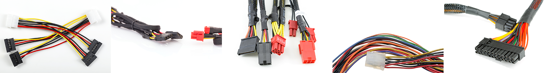
High-voltage connectors are mainly used in high-voltage and high-current circuits of electric vehicles. They work with wires to transport the energy of the battery pack through different electrical circuits to various components in the vehicle system, such as battery packs, motor controllers, and DCDC converters. high-voltage components such as converters and chargers.
At present, there are three main standard systems for high-voltage connectors, namely LV standard plug-in, USCAR standard plug-in, and Japanese standard plug-in. Among these three plug-ins, LV currently has the largest circulation in the domestic market and the most complete process standards.
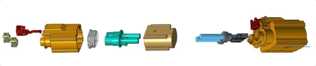
High voltage connector assembly process diagram
Basic structure of high voltage connector
High-voltage connectors are mainly composed of four basic structures, namely contactors, insulators, plastic shells and accessories.
(1) Contacts: core parts that complete electrical connections, namely male and female terminals, reeds, etc.;
(2) Insulator: supports the contacts and ensures the insulation between the contacts, that is, the inner plastic shell;
(3) Plastic shell: The shell of the connector ensures the alignment of the connector and protects the entire connector, that is, the outer plastic shell;
(4) Accessories: including structural accessories and installation accessories, namely positioning pins, guide pins, connecting rings, sealing rings, rotating levers, locking structures, etc.
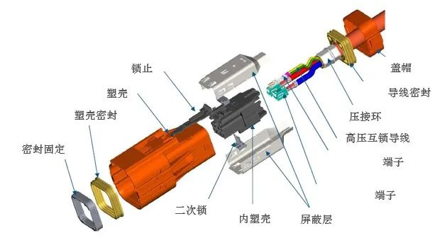
High voltage connector exploded view
Classification of high voltage connectors
High voltage connectors can be distinguished in a number of ways. Whether the connector has a shielding function, the number of connector pins, etc. can all be used to define the connector classification.
1. Whether or not there is shielding
High-voltage connectors are divided into unshielded connectors and shielded connectors according to whether they have shielding functions.
Unshielded connectors have a relatively simple structure, no shielding function, and relatively low cost. Used in locations that do not require shielding, such as electrical appliances covered by metal cases such as charging circuits, battery pack interiors, and control interiors.
Examples of connectors with no shielding layer and no high-voltage interlock design
Shielded connectors have complex structures, shielding requirements, and relatively high costs. It is suitable for places where shielding function is required, such as where the outside of electrical appliances is connected to high-voltage wiring harnesses.
Connector with shield and HVIL design Example
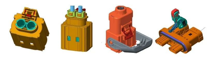
2. Number of plugs
High-voltage connectors are divided according to the number of connection ports (PIN). Currently, the most commonly used ones are 1P connector, 2P connector and 3P connector.
The 1P connector has a relatively simple structure and low cost. It meets the shielding and waterproofing requirements of high-voltage systems, but the assembly process is slightly complicated and the rework operability is poor. Generally used in battery packs and motors.
2P and 3P connectors have complex structures and relatively high costs. It meets the shielding and waterproofing requirements of high-voltage systems and has good maintainability. Generally used for DC input and output, such as on high-voltage battery packs, controller terminals, charger DC output terminals, etc.
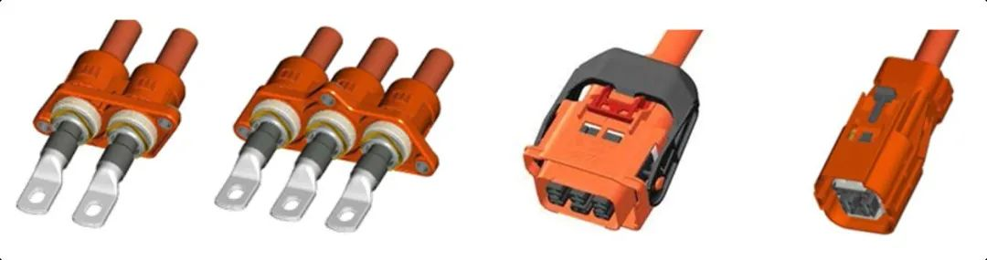
1P/2P/3P high voltage connector example
General requirements for high voltage connectors
High-voltage connectors should comply with the requirements specified by SAE J1742 and have the following technical requirements:

Technical requirements specified by SAE J1742
Design elements of high voltage connectors
The requirements for high-voltage connectors in high-voltage systems include but are not limited to: high voltage and high current performance; the need to be able to achieve higher levels of protection under various working conditions (such as high temperature, vibration, collision impact, dustproof and waterproof, etc.) ; Have installability; have good electromagnetic shielding performance; the cost should be as low as possible and durable.
According to the above characteristics and requirements that high-voltage connectors should have, at the beginning of the design of high-voltage connectors, the following design elements need to be taken into consideration and targeted design and test verification are carried out.

Comparison list of design elements, corresponding performance and verification tests of high-voltage connectors
Failure analysis and corresponding measures of high-voltage connectors
In order to improve the reliability of connector design, its failure mode should first be analyzed so that corresponding preventive design work can be done.
Connectors usually have three main failure modes: poor contact, poor insulation, and loose fixation.
(1) For poor contact, indicators such as static contact resistance, dynamic contact resistance, single hole separation force, connection points and vibration resistance of components can be used to judge;
(2) For poor insulation, the insulation resistance of the insulator, the time degradation rate of the insulator, the size indicators of the insulator, contacts and other parts can be detected to judge;
(3) For the reliability of the fixed and detached type, the assembly tolerance, endurance moment, connecting pin retention force, connecting pin insertion force, retention force under environmental stress conditions and other indicators of the terminal and connector can be tested to judge.
After analyzing the main failure modes and failure forms of the connector, the following measures can be taken to improve the reliability of the connector design:
(1) Select the appropriate connector.
The selection of connectors should not only consider the type and number of connected circuits, but also facilitate the composition of the equipment. For example, circular connectors are less affected by climate and mechanical factors than rectangular connectors, have less mechanical wear, and are reliably connected to the wire ends, so circular connectors should be selected as much as possible.
(2) The greater the number of contacts in a connector, the lower the reliability of the system. Therefore, if space and weight allow, try to choose a connector with a smaller number of contacts.
(3) When selecting a connector, the working conditions of the equipment should be considered.
This is because the total load current and maximum operating current of the connector are often determined based on the heat allowed when operating under the highest temperature conditions of the surrounding environment. In order to reduce the working temperature of the connector, the heat dissipation conditions of the connector should be fully considered. For example, contacts farther from the center of the connector can be used to connect the power supply, which is more conducive to heat dissipation.
(4) Waterproof and anti-corrosion.
When the connector works in an environment with corrosive gases and liquids, in order to prevent corrosion, attention should be paid to the possibility of installing it horizontally from the side during installation. When conditions require vertical installation, liquid should be prevented from flowing into the connector along the leads. Generally use waterproof connectors.
Key points in the design of high-voltage connector contacts
Contact connection technology mainly examines the contact area and contact force, including the contact connection between terminals and wires, and the contact connection between terminals.
The reliability of contacts is an important factor in determining system reliability and is also an important part of the entire high-voltage wiring harness assembly. Due to the harsh working environment of some terminals, wires and connectors, the connection between terminals and wires, and the connection between terminals and terminals are prone to various failures, such as corrosion, aging, and loosening due to vibration.
Since electrical wiring harness failures caused by damage, looseness, falling off, and failure of contacts account for more than 50% of failures in the entire electrical system, full attention should be paid to the reliability design of the contacts in the reliability design of the vehicle's high-voltage electrical system.
1. Contact connection between terminal and wire
The connection between terminals and wires refers to the connection between the two through a crimping process or an ultrasonic welding process. At present, the crimping process and ultrasonic welding process are commonly used in high-voltage wire harnesses, each with its own advantages and disadvantages.
(1) Crimping process
The principle of the crimping process is to use external force to simply physically squeeze the conductor wire into the crimped part of the terminal. The height, width, cross-sectional state and pulling force of terminal crimping are the core contents of terminal crimping quality, which determine the quality of crimping.
However, it should be noted that the microstructure of any finely processed solid surface is always rough and uneven. After the terminals and wires are crimped, it is not the contact of the entire contact surface, but the contact of some points scattered on the contact surface. , the actual contact surface must be smaller than the theoretical contact surface, which is also the reason why the contact resistance of the crimping process is high.
Mechanical crimping is greatly affected by the crimping process, such as pressure, crimping height, etc. Production control needs to be carried out through means such as crimping height and profile analysis/metallographic analysis. Therefore, the crimping consistency of the crimping process is average and the tool wear is The impact is large and the reliability is average.
The crimping process of mechanical crimping is mature and has a wide range of practical applications. It is a traditional process. Almost all large suppliers have wire harness products using this process.

Terminal and wire contact profiles using crimping process
(2) Ultrasonic welding process
Ultrasonic welding uses high-frequency vibration waves to transmit to the surfaces of two objects to be welded. Under pressure, the surfaces of the two objects rub against each other to form fusion between the molecular layers.
Ultrasonic welding uses an ultrasonic generator to convert 50/60 Hz current into 15, 20, 30 or 40 KHz electrical energy. The converted high-frequency electrical energy is converted again into mechanical motion of the same frequency through the transducer, and then the mechanical motion is transmitted to the welding head through a set of horn devices that can change the amplitude. The welding head transmits the received vibration energy to the joint of the workpiece to be welded. In this area, the vibration energy is converted into heat energy through friction, melting the metal.
In terms of performance, the ultrasonic welding process has small contact resistance and low overcurrent heating for a long time; in terms of safety, it is reliable and not easy to loosen and fall off under long-term vibration; it can be used for welding between different materials; it is affected by surface oxidation or coating Next; the welding quality can be judged by monitoring the relevant waveforms of the crimping process.
Although the equipment cost of the ultrasonic welding process is relatively high, and the metal parts to be welded cannot be too thick (generally ≤5mm), ultrasonic welding is a mechanical process and no current flows during the entire welding process, so there is no The issues of heat conduction and resistivity are the future trends of high-voltage wire harness welding.
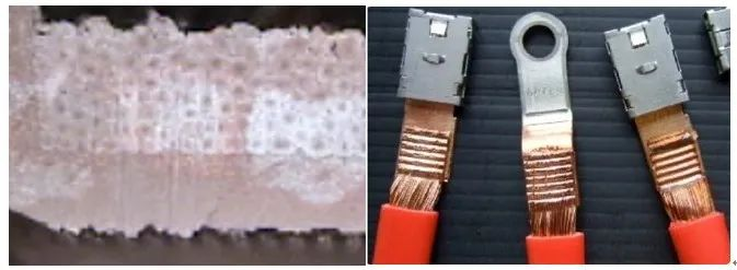
Terminals and conductors with ultrasonic welding and their contact cross-sections
Regardless of the crimping process or ultrasonic welding process, after the terminal is connected to the wire, its pull-off force must meet the standard requirements. After the wire is connected to the connector, the pull-off force should not be less than the minimum pull-off force.
Post time: Dec-06-2023