
1. Equipment
1. Equipment for measuring crimp height and width
2. A tool to open the crimp wings, or other suitable method that can open the crimp wings of the insulation layer without damaging the conductor core. (Note: You can avoid the step of opening the plastic wire crimping wings by using a non-crimping insulation method while crimping the core wires)
3. Force tester (tensile machine)
4. Head stripper, needle nose pliers and/or diagonal pliers
2.Samples
Each tested crimping height requires at least 20 samples for testing (at least 3 crimping heights are required, and 5 crimping height samples are usually provided for better selection). For multi-core parallel crimping with more than one wire diameter The line needs to add samples
3. Steps
1. During the pull-out force test, the insulation crimping wings need to be opened (or not crimped).
2. The pull-out force test requires pre-tightening the wire (for example, in order to prevent incorrect jerking before the pull-out force test, the wire needs to be tightened before the test).
3. Use a micrometer to record the core wire crimping height and width of each sample.
4. If the insulation crimp wing does not open, use a crimp remover to obtain other suitable tools to open it to ensure that the pulling force only reflects the core wire crimp connection performance.
5. Visually identify the area where the crimping wings are open to ensure that the core wire is not damaged. Do not use if damaged.
6. Measure and record the tensile force of each sample in Newtons.
7. The axial movement rate is 50~250mm/min (100mm/min is recommended).
8. For 2-wire parallel voltage, 3-wire parallel voltage or multi-wire parallel voltage, the parallel conductors are all below 1 mm². Pull the smallest wire. (For example, 0.35/0.50 parallel pressure, pull 0.35 mm² wire)
For 2-wire parallel voltage, 3-wire parallel voltage or multi-wire parallel voltage, and the parallel conductor content is greater than 1mm², it is necessary to pull one with the smallest cross-section and one with the largest cross-section.
Some examples:
For example, for 0.50/1.0 parallel pressure, both wires must be tested separately;
For 0.5/1.0/2.0 three-parallel pressure, pull the 0.5mm² and 2.0mm² wires;
For 0.5/0.5/2.0 three parallel voltages, pull the 0.5mm² and 2.0mm² wires.
Some people may ask, what if the three-point wires are all 0.50mm²? There is no way. It is recommended to test all three wires. After all, we can’t think of any problems.
Note: In this case, 20 samples are required for each wire size test. Testing of each tensile value requires the use of a new sample.
9. Use the following formula to calculate the average and standard deviation (use EXCEL or other suitable spreadsheets to calculate the average and standard deviation of the tensile results obtained by the calculation step). The report reflects the minimum, maximum, and average values of each crimping height. Value (`X), standard deviation (s), and mean minus 3 times the standard deviation (`X -3s).
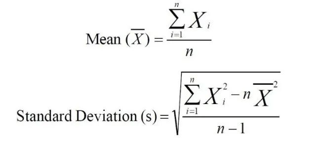
Here, XI = each tensile force value, n = number of samples
Formulas A and B - mean and standard deviation of pull-out force criterion
10. The report should document the results of all visual inspections.
4. Acceptance standards
For the (`X-3s) calculated using formulas A and B, it must be consistent with or greater than the corresponding tensile force values in tables A and B. For wires with wire diameter values not listed in the table, the linear interpolation method in Table A and Table B can be used to calculate the corresponding tension value.
Note: The tensile force value is used as a sign of crimping quality. When the pulling force cannot reach the standards listed in the table due to the wire pulling force (not related to crimping), it needs to be solved by engineering changes to improve the wire.
Table A and Table B - Pullout Force Requirements (mm and Gauge Dimensions)
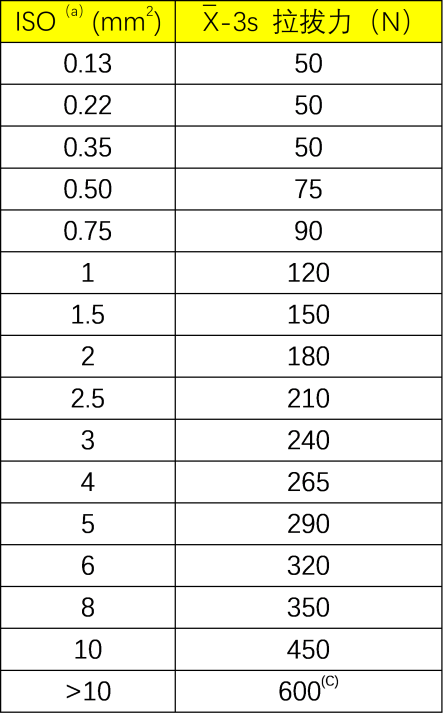
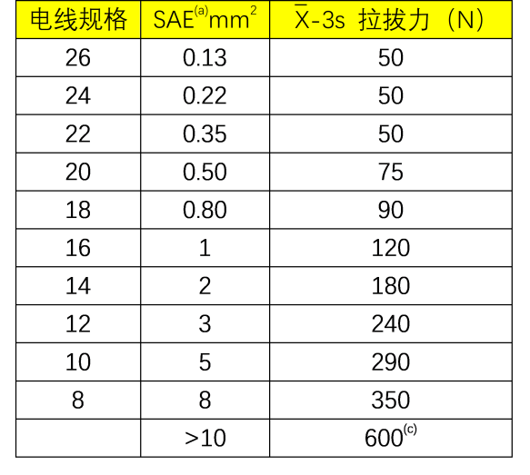
ISO standard dimensions are based on ISO 19642 Part 4, SAE is based on SAE J1127 and J1128.
Wire sizes of 0.13mm2 (26 AWG) or smaller that require special handling and control are not included in this standard.
For > 10mm2 the minimum value required is achievable. There is no need to completely pull it off, and there is no need to calculate the value of (`X-3s).
Post time: Nov-28-2023